Bits & Bytes

Posts Tagged ‘transformation’

Programming a 3D Scene in WPF with C#

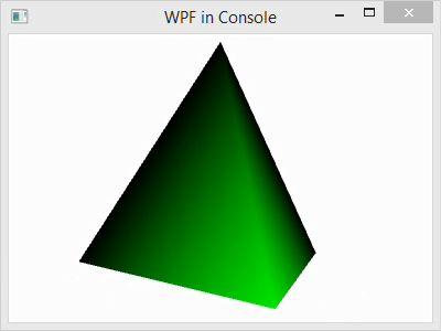
In this post, I explain the basic Windows Presentation Foundation programming elements of a 3D scene in C#. The C# code that I use for demonstration creates a simple tetrahedron model and rotates it around the vertical axis.

RotatingTetra

To create the project, follow these steps:

  1. Begin with the project from our prior blog post, or create a new WPF project.
    OpenProject
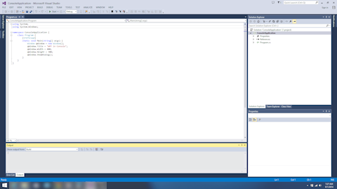
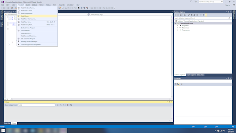
  2. Add a class file to the project: left-click PROJECT in the menubar and left-click Add Class… in the submenu.
    ProjectAddClass
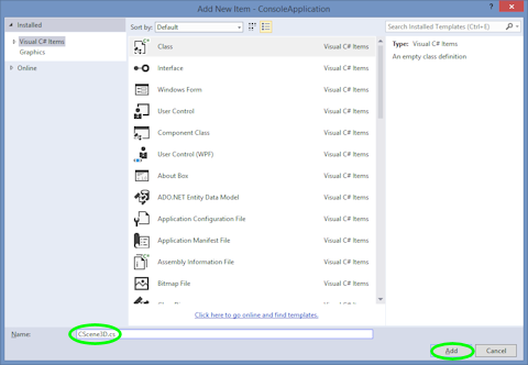
  3. This pops up the Add New Item dialog. Select Installed->Visual C# Items in the left-hand pane.
    VisualCsharpItems
  4. Then left-click Class in the center pane to select it.
    Class
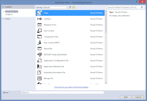
  5. Finally, rename the class by left-clicking the text box next to Name: at the bottom of the window and entering CScene3d.cs. Finish adding the class by left-clicking the Add button.RenameClass
  6. Next, copy the code for “CScene3D.cs” below into the file of the same name in your project.
  7. Finally, finish the code by adding this line to “Program.cs” as shown in the code below to allow the window to display the 3D scene:
    qWindow.Content = TestScenes.Test5();
  8. Compile and execute the program by left-clicking DEBUG in the menubar and left-clicking Start Without Debugging in the submenu. After a few seconds, the code will be compiled and a window will pop up displaying a rotating tetrahedron.DemoImage

The WPF scene creation in “CScene3D.cs” consists of a few basic steps, which can be outlined as follows:


  1. Create a camera and add it.
  2. Create a lighting model and add it.
  3. Create a geometric model and add it
    1. Create points, triangles, and normals
    2. Set the material properties
    3. Create and apply transforms

For simplicity, I have skipped some steps, like adding normals, and accepted default values for much of the rest. At the end, I have collected components to added them appropriately. Pay close attention to that.

Program.cs

using System;
using System.Windows;

namespace ConsoleApplication {
    class Program {
        [STAThread]
        static void Main(string[] args) {
            Window qWindow = new Window();
            qWindow.Title = "WPF in Console";
            qWindow.Width = 400;
            qWindow.Height = 300;
            qWindow.Content = CScene3D.Test();
            qWindow.ShowDialog();
        }
    }
}

CScene3D.cs

using System;
using System.Windows;
using System.Windows.Controls;
using System.Windows.Media;
using System.Windows.Media.Media3D;
using System.Windows.Media.Animation;

namespace ConsoleApplication {
    class CScene3D {
        // Animation - Tetrahedron (upright, looking slightly up from below)
        public static Viewport3D Test() {

            // Define the camera
            PerspectiveCamera myPCamera = new PerspectiveCamera();
            myPCamera.Position = new Point3D(0, .2, 3);

            // Define a lighting model
            DirectionalLight myDirectionalLight = new DirectionalLight();

            // Define the geometry
            const double kdSqrt2 = 1.4142135623730950488016887242097;
            const double kdSqrt6 = 2.4494897427831780981972840747059;
            // Create a collection of vertex positions
            Point3DCollection myPositionCollection = new Point3DCollection();
            myPositionCollection.Add(new Point3D(0.0, 1.0, 0.0));
            myPositionCollection.Add(new Point3D(2.0 * kdSqrt2 / 3.0, -1.0 / 3.0, 0.0));
            myPositionCollection.Add(new Point3D(-kdSqrt2 / 3.0, -1.0 / 3.0, kdSqrt6 / 3.0));
            myPositionCollection.Add(new Point3D(-kdSqrt2 / 3.0, -1.0 / 3.0, -kdSqrt6 / 3.0));
            // Create a collection of triangle indices
            Int32Collection myTriangleIndicesCollection = new Int32Collection();
            // Triangle
            myTriangleIndicesCollection.Add(0);
            myTriangleIndicesCollection.Add(2);
            myTriangleIndicesCollection.Add(1);
            // Triangle
            myTriangleIndicesCollection.Add(0);
            myTriangleIndicesCollection.Add(1);
            myTriangleIndicesCollection.Add(3);
            // Triangle
            myTriangleIndicesCollection.Add(0);
            myTriangleIndicesCollection.Add(3);
            myTriangleIndicesCollection.Add(2);
            // Triangle
            myTriangleIndicesCollection.Add(1);
            myTriangleIndicesCollection.Add(2);
            myTriangleIndicesCollection.Add(3);
            MeshGeometry3D myMeshGeometry3D = new MeshGeometry3D();
            myMeshGeometry3D.Positions = myPositionCollection;
            myMeshGeometry3D.TriangleIndices = myTriangleIndicesCollection;
            // Apply the mesh to the geometry model.
            GeometryModel3D myGeometryModel = new GeometryModel3D();
            myGeometryModel.Geometry = myMeshGeometry3D;

            // Define the material for the geometry
            SolidColorBrush qColorBrush = new SolidColorBrush(Color.FromArgb(255, 0, 255, 0));
            DiffuseMaterial myMaterial = new DiffuseMaterial(qColorBrush);
            myGeometryModel.Material = myMaterial;

            // Define the transformation, if any. In this case, we use an animated transformation
            RotateTransform3D myRotateTransform = 
                new RotateTransform3D(new AxisAngleRotation3D(new Vector3D(0, 1, 0), 1));
            DoubleAnimation myAnimation = new DoubleAnimation();
            myAnimation.From = 1;
            myAnimation.To = 361;
            myAnimation.Duration = new Duration(TimeSpan.FromMilliseconds(5000));
            myAnimation.RepeatBehavior = RepeatBehavior.Forever;
            myRotateTransform.Rotation.BeginAnimation(AxisAngleRotation3D.AngleProperty, myAnimation);
            myGeometryModel.Transform = myRotateTransform;

            // Collect the components
            Model3DGroup myModel3DGroup = new Model3DGroup();
            myModel3DGroup.Children.Add(myDirectionalLight);
            myModel3DGroup.Children.Add(myGeometryModel);
            ModelVisual3D myModelVisual3D = new ModelVisual3D();
            myModelVisual3D.Content = myModel3DGroup;
            Viewport3D myViewport3D = new Viewport3D();
            myViewport3D.Children.Add(myModelVisual3D);
            myViewport3D.Camera = myPCamera;

            return myViewport3D;
        }
    }
}

Perspective Projections in 3D with Actionscript 3.0

The most fundamental transformation in 3D graphics is the perspective transformation that projects points in 3D space onto the 2D image plane. In Actionscript, this is referred to as a Perspective Projection. This transformation is absolutely essential to creating an image from a 3D model. Most models are composed of sets of points. So, we will show how to project a single 3D point onto a 2D image. Once you know how to project a point, you can project virtually any complex object in 3D. For example, you can project a polygon by projecting each vertex, individually. Once the vertices are projected, you can connect them to create the projected polygon.

"Basic 1D Perspective Transformation"

Before we get into 3D, we want to consider how we can project a point in 2D onto a 1D line segment. This will demonstrate the essence of the problem and make the 3D case much easier to understand. So, we begin with 2D plane, and we want to project it onto the x-axis or the line y = 0. Every perspective projection has a viewpoint, which represents the observer’s eye. In this case, we set the viewpoint at (0, -1) and say that we are looking down the y-axis in the direction in which y is increasing (as shown by the white arrow). Now any point in the 2D can be projected onto our 1D image line given by the x-axis. For example, the point P’ = (1.5, 2) gets projected, by triangle similarity, onto the x-axis at P” = (.5, 0), where

x” = x’*(1/(2 + 1))

= 1.5*(1/3)

= .5

In general, a point (x’, y’) is transformed to (x”, 0) by x” = x’*(1/(y’ + 1)).

"Generalized 1D Perspective Projection"

This result can be further generalized by allowing the viewpoint to be anywhere on the negative y-axis. Here’s we have the viewpoint at (0, -f), and f is refered to as the focal length. Here, the point (x’, y’) is transformed to (x”, 0) by x” = x’*(f/(y’ + f)) in much the same way as before.

"1D Image with Field of View"

Unlike the x-axis, images have finite length. Here, we used the interval [-w/2, w/2] to represent a one dimensional image with its width equal to w. If we project a point to the x-axis and it falls outside of this interval, it will not show up in our image. In this case, we say that the point is clipped. However, the finite image size presents us with an opportunity to define the field of view. The field of view is the angle θ defined at the viewpoint that encompasses the image width. By trigonometry, we have tan(θ/2) = (w/2)/f. So, the focal length, f, can be written in terms of the image width, w, and field of view like this f = w/(2*tan(θ/2)).

Next, we move to three dimensions and the default case for Actionscript. In this case, our origin is positioned in the upper-left corner of our image with the positive z-axis pointing into the screen. The image width and height are given by the stage object, and we will refer to them simply as w and h, respectively. With this, we have viewpoint located in the default position at (w/2, h/2, -f). The point (w/2, h/2) defines the vanishing point of the image and is called the projection center in Actionscript. By default, the field of view is 55 degrees, and the focal length is calculated from the field of view as f = w/(2*tan(θ/2)), which follows from the fact that tan(θ/2) = w/(2*f). In 3D, the projection of the 3D point P’ = (x’, y’, z’) to P” = (x”, y”, 0) in the 2D image space defined by the xy-plane or z = 0 is accomplished with the following equations

x” = w/2 + (x’ – w/2)*(z’/(z’ + f))

y” = h/2 + (y’ – h/2)*(z’/(z’ + f))

"Default Actionscript Perspective Projection"

In Actionscript, perspective transformations are accomplished by the PerspectiveProjection class, which has three members named: fieldOfView, focalLength, and projectionCenter. These properties correspond to the field of view, the focal length, and the projection center, respectively.

Keep in mind that the focal length and the field of view are not independent, but are related by the formula above. So, changing the value of one will change the other. The field of view is not used in the projection equations, but it is used as a convenient way to understand how projections work and set the focal length.


© 2007–2024 XoaX.net LLC. All rights reserved.